Rolling Robots
Team members:
Ozguc Capunaman(MSCD 2019), Scott Leinweber(HCI 2018), Atefeh Mahdavi

How Can Robots Be Used to Record Video?
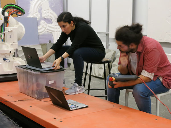
This project examines using industrial robotics for media creation, specifically DSLR video camera control and recording. Both digitally programmed camera paths and hand held capture are explored, as well as a post-process technique for VFX over the environment. Some questions we hope to answer:
How best can a director make a digital camera path?
How can motion capture be used to define a shot?
Which types of shots cater to robotic control?
How does speed affect quality and composition?
How can the virtual environment be leveraged to add digital models to the shot?

Objectives
This project examines using industrial robotics for media creation, specifically DSLR video camera control and recording. Controlling focal length of the lens is a chief aim of this project and allows us to input the point of focus as a distance, which the lens then focuses to. This requires a follow-focus(a mechanism for smooth focusing used for film), some custom gearing, and custom software. The first step is to select a lens and calibrate it. DSLR lenses (we are using Canon EF-lenses) are often focused by hand, with the operator controlling the focal length by rotating the barrel of the lens to a specific depth. Our system takes a digital number of the focal distance (e.g. 1850mm) and translates it into an angle of rotation (64.5 degrees) and makes the necessary rotation on the lens.

Tool Prototyping
The tool is a combination of industry-standard 15mm rails, often used for mounting filters and accessories to the front of a DSLR camera, and custom electronics, all mounted on a 12” x 6” plywood base. This base holds together all of the components and mounts flush to an ATI robot arm mounting plate on the robot at typical “tool0”. We used a cheap aluminum rail system purchased off eBay for ~$40. This included an adjustable mounting plate for the camera, two 15mm rails, and a follow focus. The follow focus is a cheaper imitation of a nicer, side-pulling manual follow focus that allowed us to quickly prototype a digital motor armature that we could program and control digitally. After some iteration prototyping on this follow-focus, we ended up deciding to design our own. After a number of experiments and calibrations, we decided to bypass the purchased follow-focus, and create our own. The purchased follow focus had some wiggle in it,in addition to being quite large and cumbersome on the robot. With a stepper motor on the side of the rig, it would make the tool wide and introduce a large moment force on the side. To short circuit these factors, we designed a few iterations of our own gearing and stepper chassis.

Lens Calibration
While we made some initial calibration studies before hooking up the motor to the follow focus, the real calibration requires the translation of digital steps controlling the motor, which in turn focus the lens. With the Arduino hooked up to the stepper and the camera fixed in position on the rails, we laid out a field of markers at every 100mm from the camera sensor. The stepper is set to zero steps, and engaged with the lens gear with the lens set to its closest focus depth possible (often around 300mm). As steps are One person enters steps into a command line in Arduino, adding or subtracting as needed, while another person is looking into the camera’s LCD display, zoomed into to 10x zoom, verifying the focus clarity of the stepper position. When the camera is focused precisely at a set focal distance (i.e. 600mm), the computer operator would record the number of steps from zero on the stepper, and after aggregating all of them, plot a line graph from 300mm to infinity.


Integration
One of the biggest challenges in our projects was to integrate all the components (Maya, Hal, Arduino, Robot) together. Maya provides more cinematic control, as it is often used for animation and provides fine-grain motion control via a curves editor. The frame is pre-programmed as a virtual camera in this modeling software and exported as a series on planes to run as the tool path. We wrote a code to parse the planes to Grasshopper and then we could incorporate them with HAL. We used analogue IO on ABB robot (Pin G and P) for sending signals to Arduino. We modifies our Arduino script to change the rotation based on the analogue voltage (0-5V) was being sent by ABB robot. Then we did the final lens calibration to find the correlation between voltage and rotation.. We experienced hardware interventions, signal instability and delays in Arduino. However, with the time and resources we had, the final results were exciting.


